
Outdoor Navigation of a Mobile Robot
Outdoor Navigation of a Mobile Robot Platform Using a Low Cost High Precision RTK-GPS and Obstacle Avoidance System
Under supervision of:
Prof. Dr.-Ing. Klaus-Dieter Kuhnert
Dipl. -Inform. Klaus Müller
Submitted by:
Charan Ram Akupati
Matrikel Nr: 1059977
Introduction
The main objective of mobile robotics is to develop robots that are capable of moving autonomously in unknown environments. Mobile robots are independent robots, which are designed to perform certain tasks. On the basis of type of business functions, mobile robots are outdoor and indoor mobile robots. However, mobile robots are very expedient in domestic, medical, military and space purposes. These are designed with the integration of a variety of sensors makes use in a wide variety of applications in structured as well as in unstructured environments. Indoor robots can be used for floor cleaning, material handling and industrial applications. Outdoor robots can be used for patrol, surveillance, exploring planets in military and space functions. In order to accomplish the assigned tasks, the outdoor robots should have an accurate autonomous navigation system.
In recent years, an autonomous navigation system is a challenging task in the field of mobile robotics. The navigation system that implemented in mobile robots should be capable to drive the robot in an unknown and unstructured environment. Mobile robot navigation is divided mainly two categories, such as indoor and outdoor navigation. The developed navigation drives and controls the robot directions from starting terminal to end terminal. Among all, vision based and sensor based navigation system is well studied. Vision-Based navigation systems built through creating a visual map of unknown environment, with 2D or 3D laser scanners and cameras. Whereas, the sensor based navigation systems constructed by laser scan ranges and ultrasonic sensors.
Furthermore, the navigation system includes localization and path planning. In outdoor navigations, GPS useful in localization, laser range finders and IMU sensors are addressing the path planning. However, the robot should know its geographical location on the planet and orientation to function autonomously. In indoor navigation, the robots are administered and path will be designed with the help of painting lines on the floor through fixing reference markers. In the driving path, cameras and laser scanners create a map and overcome the obstacles.
The current project is focused towards developing, an intelligent outdoor navigation system for the Phaethon robot, at the University of Siegen, Germany. The RTK GPS system, IMU sensor, and 2D laser scanner will be integrated with the robot. The desired navigation system should locate the robot through RTK GPS system; the IMU sensor determines the orientation, 2D laser scanner detects the obstacles and navigates the robot through way-point system.
Objective
The objective of the current project is to acquire an intelligent navigation system for outdoor mobile robot Phaethon. In order to build the desired navigation system, the integration of a RTK GPS system, IMU sensor with the robot is a vital step. The important parameters to study, and incorporate in the navigation system are following,
- RTK GPS module To locate the robot and to plot on a satellite map.
- IMU sensor To find the orientation of the robot.
- Graphical User Interface (GUI) To control the robot.
- Processing high resolution satellite images of geographical positions with particular latitude and longitude coordinates. Plotting way points on the satellite image.
- Designing and developing the obstacle avoidance algorithm to drive the robot .
Concept of the Project
In order to achieve high precision and accuracy in the range of few centimeters, so as to satisfy this requirement a highly accurate RTK GPS system should be incorporated in this project. The robot initial position is plotted on the off-line satellite map, using RTK GPS. On plotting the current position of the robot it awaits user to define the way-points. After receiving the way-point user input, the robot initiates the path planning process. In this process, it identifies its current orientation using the IMU sensor data. A way-point angle is automatically calculated based on the robot current position and the next destination to be reached by it. Based on the way-point angle and IMU data, driving angle called 'steering-angle' will be calculated, a path is estimated to the user defined way-point. Using this estimated path, the robot starts moving towards the destination point. A laser scanner is mounted on the robot and made use to detecting any obstacles on its travelling path.
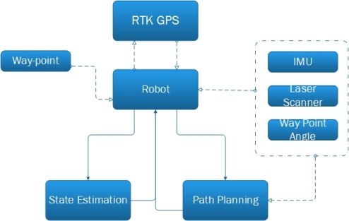
Figure 1: Block diagram of project
Robot automatically estimates a new path on detecting an obstacle and continues its further motion. Besides this process, the robot calculate the distance between the way-point and its current position and estimates its state with respect to way-point. On reaching the certain way-point circle, it resets its state and reinitiates the path planning process for the next way-point. Implementation of this ideology is depicted in fig. 1. Outdoor navigation process is extremely based on the relative position between the two RTK GPS modules, IMU data and on calculated steering angle towards way-points. The data flow in this navigation system is explained in the flow chart as shown in the fig. 2.
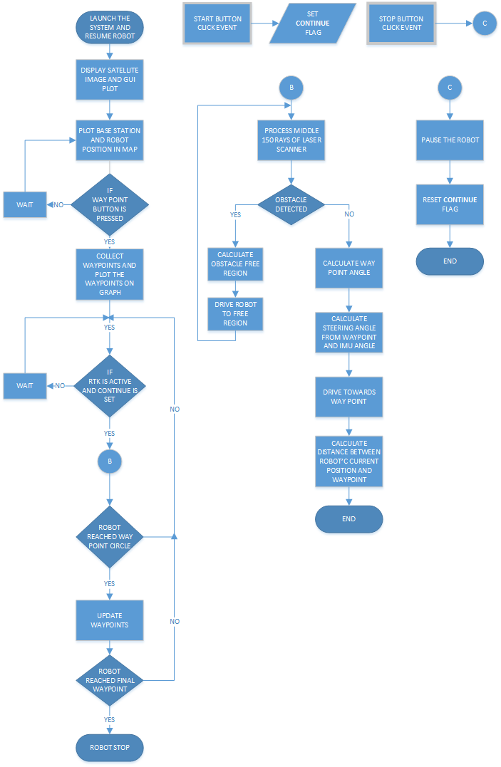
Figure 2: Flow chart of Navigation System
Testing and Results
Testing has been done in two parts such as with and without obstacle presence. It is tried to drive the robot towards different radius of way point circles such as 0.7 meters, 1.5 meters and 2 meters. In this algorithm, the way point circle was considered as radius of 70 centimeters. After plotting way-points and robot initial position on the map, on start button click, the robot start moves towards the first way point and path was plotted as shown in the fig.3. Every time the algorithm calculates the distance between in its current position and the way-point. If the distance is less than 70 centimeters, then the robot moves towards next way point. And finally when the robot reaches final way point, it stops.
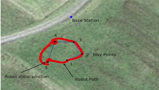
Figure 3: Tracking robot path without obstacle presence
Fig. 4 shows an obstacle between the second and third way-points. During the path planning between second and third way point, the robot steers to right direction in order to avoid the obstacle. And again the robot plans its path towards the third way point after avoiding the obstacle.
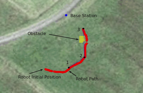
Figure 4: Tracking robot path with obstacle avoidance